Wednesday, November 14, 2012

F.Y.P.2 ~ 14th Week: Presentation and Competition Moment

The day of finale has come as we all need to present our FYP result to our selected assessor. Each of the student will be assessed by two lecture and the lecture who assessing me is:

~ Mdm Nurul Rodziah Bt. Abdul Ghafar
~ Mdm Azura Bt Hamzah

I've been assessed well by the lectures as they ask about my project from beginning till I've succeed to produce the robot of my own.

After my presentation, me and my friend proceed to competition track to start the challenge. Each of student's robot who compete have their own ability and unique design.

Each competitor preparing their robot for the race

The winner will be calculate by how many turn the robot can move in limited time.

Alhamdulillah, at last I get 3rd place in the race when I completed one turn within 3 minutes. It was very challenging as the obstacle sensor circuit was torn out by sudden, but the robot still making its move till the end. I'm really gratefully to win on 3rd place in this competition.

Next, I need to start my progress on completing the FYP report as it need to be submit by week 17.

Tuesday, November 13, 2012

F.Y.P.2 ~ 13th Week: Representing Poster

Its week 13, only one week left for the FYP Presentation that will be held on Thursday. A poster is one of the criteria needed during the presentation. Below is the poster that I have designed and it been approved by my supervisor.


As been advise by my supervisor, I have added Block Diagram, Application and Result into the poster.

After presenting my FYP, me and my friend's robot will be compete in the Intersection Section Challenge as to challenge the robot speed and time by representing for each department. With the Test G-00 robot performance, I'm hoping for winning in the competition. Just wish me luck :)

F.Y.P.2 ~ 12th Week: Test G-00 Way To Go! (Video)

This week, I will presenting to you a video of Test G-00

Please enjoy the video, even thou it was low quality :)


For now, I was preparing a draft for the poster to be presented on week 14. So far the poster seems to be approved by my supervisor. 

Next week I will upload to show my poster that will be use on 14th week.

F.Y.P.2 ~ 11th Week: Test G-00 Way To Go!

This week gonna be my happiest moment in my life as the robot can move smoothly and accordingly to what I desired for. After my programming issue was solve, I have tried to make a housing as a body to cover the circuit attached to the robot. The housing was made from recycle boxes.

This is the completed six-legged robot I named as Test G-00

As my programming issue has been solve, I can say that I have completed my six-legged robot and I can start to focus on presentation which will be held on week 14.

F.Y.P.2 ~ 10th Week: Re-Program

From the update last week, I found out that my programming is faulty when the robot movement when wrong and not according to what I desire. So, I have take an advise from my friend to check for any error within the programming.

I've placed the LCD on the circuit to make programming more easy.

After I check the program, we found there was an error on the 2nd servo (left leg). It does not following the servo controller command as the obstacle sensor has submit its signal to the servo controller for the left leg to change its movement. So, I have re-program it and I will check again either the servo can move accordingly. If not, I may need to re-program again.

F.Y.P.2 ~ 9th Week: Burn Mode

Today, I will proceed to burn the program into the PIC microcontroller. But before I start, I need to find a suitable USB to plug in toward the circuit from my desktop.

Below is a step taken to burn the program into the PIC:

First Install WinPic800 which able to detect the PIC. Now click the icon as shown above and the software will detect the type of the PIC.

Next, I need to write a HEX code. So I need to open a HEX file by clicking the icon shown. Browse and open the hex file.


After that, I will program the file to PIC by click the icon as above.

A confirmation window will appear and click Yes to proceed programming the PIC.

Now the program will be burn into the circuit.

When it is completed, the window will show the status. Click Accept and the PIC ready to be plug out.

Now as the circuit is completed with the program, I need to assemble the circuit on the mechanical part.

Next I will test the robot either the program is suitable with the movement that I desire or not.


F.Y.P.2 ~ 8th Week: Programming Tine

As I using PIC16F877 develop by Microchip, I will perform the programming in a software called as MPLAB IDE which can be download from www.microchip.com.

For more understanding, below is the step taken to perform programming in MPLAB:
(Please click on the picture for better view)

Before start, please create a new folder in C:\ drive and rename the folder accordance to the project name/title. This folder is now become our project folder.


Copy the given ASM code into the new project folder and rename it
with the name that related.


Now, Open the MPLAB and go to Project Menu and Click “Project Wizard”

Click “Next”

Now, please select devices that we want to program. As for my project, I will choose 16F877A

After that, select language tool suite as shown above.


Next, browse where to locate our new MPLAB project and write a name for the project.


Now, select the existing assembly code/project and click “add” to insert to new MPLAB project.


And now the project wizard is completed. Check the summary and click “Finish”

The new MPLAB project should look like the picture above


Now is the step to build a program in MPLAB:

To Build your new project, go to menu “Project” and click on “Build All”


Above is the succeeded result after Build process


I will program it according to what I desire as to program the movement for my six-legged robot. 

After I finish the programming, I will burn it into the circuit which already build on last week.


F.Y.P.2 ~ 7th Week: PCB Design Part 3

This week, I have attach all of the component on to the PCB circuit as we can see from picture below:

Upper view: The red and black wire is the power supply connected to circuit.

 Bottom view: After been well solder.

When I turn ON the power, the LED of circuit is light up. Now I need to complete the programming for robot as I need to burn the program into this circuit. 

F.Y.P.2 ~ 6th Week: PCB Design Part 2

In this week, I have designed the PCB for the PIC circuit to be placed. I'm using Proteus as it is easy to design a circuit and easy to use. Below is the schematic of the circuit.

Circuit which I've designed in Proteus.

Print view of circuit schematic.

To make a PCB, the design need to be print on a transparent paper before it is affixed into PCB by going thru a UV rays process which will take about 2 minute to complete. Then the PCB will added with a liquid for etching process. The ferric chloride powder will the mixed with warm water. Then silica will detach and remove the layer by washed with clean water. After that, the PCB will be insert into a developer liquid that will silicon oxide from the PCB. Now the PCB circuit is ready to be use.

This is the PCB circuit that is ready to be use.

Next week, I will start to attach all of the component onto the PCB circuit.

F.Y.P.2 ~ 5th Week: PCB Design Part 1

Previously, I've stated will using the PIC32 series. But after discussed with my friend, they advised me to use PIC16 series that consist 40-pin.


This is because it has high performance reduce instruction set computing (RISC) CPU with operating speed up to 200ns of instruction cycle. It only have 35 of instruction set. It also has a programmable code protection.

So I have finalize to use this PIC for my robot and I will design the PCB base for the PIC16 series.

F.Y.P.2 ~ 4th Week: Mechanical Assembly Part 2

As from the last week update, I have finish assemble all the steel rod on top of the transparent plastic platform. While the servos is placed on the bottom of the plastic platform. 

Front view: I have add-on another steel plate in front as to place a sensor circuit.

Side view: The middle servo is placed with the steel rod (middle leg) that stabilize the robot

Back view: I've left a space on behind of the plastic platform as to place the sensor circuit.

The middle steel rod between two leg on both side will act like a push and puller for leg on behind.

As for now overall of the robot structure is simply look like a spider. Later on, I will design the PCB base on the PIC16 series for the robot.

Saturday, November 10, 2012

F.Y.P.2 ~ 3rd Week: Mechanical Assembly Part 1

For the past few week after I asked my friend for the robot mechanical design, I have design the base for the robot structure out from the paper.

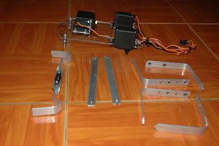
The figure below is the one that I have designed as a steel rod base will be the leg for the six-legged robot which supported by 3 servos.

The servo motors have been placed on a transparent plastic platform.

3 Servo motors with other steel plate.

This part will be placed on the middle servo as to stabilize the robot.

Next, I will combine all the steel rod with the servo motors and we shall see the assembling results on nest week.

Friday, November 2, 2012

F.Y.P.2 ~ 2nd Week: Sensor Circuit

In this week, I will try to complete the Infrared sensor circuit which will be attach to the six-legged robot.

As I mention previously, the infrared sensor is to detect the obstacle when the robot start to walk and it will send a message to the motor to move the robot as to avoid from any obstacle ahead.

Below is the picture of the circuit:~

Print view of circuit schematic.

Circuit Schematic for Sensor designed in Proteus

Back view of the PCB after solder.


Sensor Circuit (The Obstacle sensor is still unattached)

F.Y.P.2 ~ 1st Week: Structure Detail Design

While in my semester break, I have ask a help from my friend to design the mechanical part of the robot. Unfortunately, I just able to buy 3 servo motor in that time. So he tried to figure out the structure for the robot base on 3 servo motor.

He advise me to build a six legged robot which is more balance and it can move just with 3 servo motor. With this method, it gave me an advantage to cut cost from my original budget.
Spider - Six Legged Robot Design


The robot basic design was made out from SketchUp software so we can be view the structure, shape and design in 3D. Now I can figure out the tool and material that I really need to build up this robot.


Front View

Back View


Bottom View


Rear View

Upper View


So I have decided to change the design for my robot from 4-legged into 6-legged. As according to the previous plan, I may have to place 8 servo for the robot. But I'm only will use 3 servo motor into the design as to move the robot